

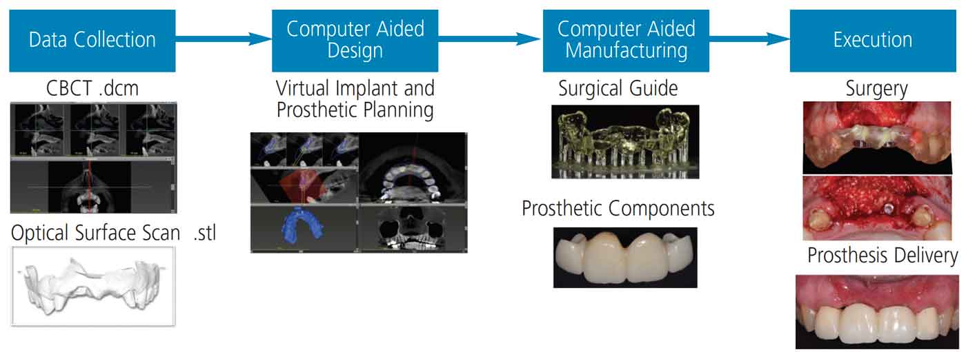
Implant therapy is considered an integral part of dental treatment for many patients. Since the introduction of implant therapy almost 30 years ago, the field has changed significantly. One change that reshaped the clinical approach to implant treatment planning and therapy was the introduction of digital technologies and workflows. Due to their advantages in accurate diagnosis, treatment planning, and executing implant procedures, digital technologies are becoming more widely utilized. Elements of a digital workflow include data collection, computer aided design/computer aided manufacturing (CAD/CAM), and implant placement (Figure 1).
The first step in the digital workflow is data collection using digital imaging, such as cone beam computed tomography (CBCT) and optical surface scanning, which includes intraoral scanning and extraoral model scanning. Intraoral or extraoral optical surface scans allow the dentist to accurately represent both teeth and soft tissue as a digital Standard Tessellation Language (STL) file. The STL file is transported to a virtual implant planning software, where the CAD process begins. The STL file is registered and merged with the Digital Imaging and Communications in Medicine (DICOM or .dcm) files obtained from the CBCT imaging. Next, implant position is planned according to appropriate anatomical and prosthetic principles. Additionally, the same software can design the prostheses, surgical templates and respective sleeves. Use of CAM processes as the final step involves subtractive or additive technology to fabricate surgical templates and implant-supported restorations.1
Accuracy of static computer assisted implant surgeries (sCAIS) is defined as deviations between the planned and fixed implant.2 Studies have shown that all sCAIS show some degree of imprecision resulting in deviations between actual and virtual implant positions.3 This can be attributed to errors in the digital workflow: data collection, transfer or processing, CAD (or virtual) implant treatment planning, CAM, and surgical execution. During data collection, accuracy of the CBCT can be affected by features of the machine, radiation exposure, software used to view DICOM data, patient movement and artifacts from restorations.4 When comparing conventional models with optical scans, in vivo data is lacking due to difficulty in obtaining a standardized protocol for model recording and reproduction. However, from the available limited data clinicians have made suggestions for achieving predictable clinical outcomes.5
When designing the virtual implant position, clinicians should keep in mind anatomical positions of adjacent teeth or implants and vital structures, such as the inferior alveolar nerve, mental nerve, maxillary sinus and nasal floor. Once the implant position is planned according to the appropriate anatomical and prosthetic considerations, the clinician can start designing the surgical template with the following considerations: type of support (bone, mucosa, tooth or fixture), sleeve-to-bone height, drilling distance, and the number of teeth used as support in a tooth-supported template.
This article will review these factors and provide clinical insight for providers who are thinking about implementing a digital workflow to achieve the best possible outcomes.
DATA COLLECTION
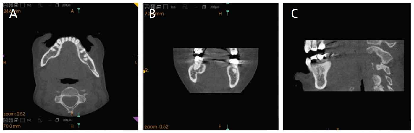
Cone beam computed tomography — This imaging modality offers numerous advantages, which include identification of pathology, vital anatomical structures, and assessing bone quality and quantity for implant planning. Three-dimensional (3D) CBCT generates a series of planar basis images that are reconstructed with special software to yield volumetric data sets of varying projections: axial, sagittal and coronal (Figures 2A through 2C).6 While considered quite accurate, various factors help determine the level of accuracy of CBCT images.7
A range of error exceeding 1 mm was usually noted while performing linear measurements of bone and anatomical structures. These errors can lead to clinical complications during surgical execution. Therefore, an agreed upon 2-mm safety zone is usually recommended when measuring how far the proposed implant is to vital anatomical structures. Other machine-dependent factors that can influence the accuracy of linear measurements include filtration, target-object and object-sensor distances, reconstruction algorithms used, and different head restraining devices.

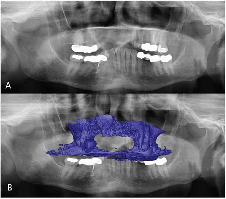
For a CBCT machine to be considered a true advantage, it should have radiation dosages less than a spiral CT machine — preferably somewhere around the equivalent of two to 10 panoramic radiographs (or 20 to 100 μSv). However, reducing the radiation dosage too much may render some images diagnostically useless. Therefore, clinicians should aim for doses that are As Low As Diagnostically Acceptable being Indication-oriented and Patient-specific, otherwise known as ALADAIP.8 Some of the techniques to minimize radiation dosage are reducing scan time, the scan arc, or field of view (FoV; Figures 3A and 3B). All of these factors have no adverse effects in terms of the accuracy of linear measurements. However, when utilizing CBCT data for guided implant planning, clinicians should keep in mind that a FoV with sufficient points to be merged with the STL file is recommended.6
Another factor that plays a role in the resolution of CBCT images, but not necessarily the accuracy of linear measurements, is voxel size, which is usually predetermined by the type of CBCT machine. A voxel is the volume element, defined in 3D space. The dimensions consist of pixels and thickness of the slice. A voxel size of 0.3 to 0.4 mm is usually sufficient to provide necessary accuracy for implant treatment planning.6,9
Scatter is a common phenomenon that usually reduces the accuracy of merging data sets and linear measurements. This usually occurs when the X-ray beam strikes high-density objects, such as amalgam restorations, crowns with metal, gutta-percha, posts, sealers or dental implants, creating a beam-hardening artifact (Figures 4A and 4B).10 Use of cotton rolls to separate maxilla from mandible is a way to minimize the effect of scatter from the opposing arch. Additionally, clinicians can use composite-resin markers on teeth to act as common landmarks in each digital data set for accurate registration.11
Movement artifacts, which usually occur when patients move, can lead to lack of sharpness in images, and therefore difficulty in merging STL and DICOM data sets. Therefore, it is important to avoid these artifacts through proper patient head immobilization and short imaging times.
Optical surface scanning — Conventional or digital impressions transfer information related to teeth, soft tissue and implant position data into stone or virtual models that are utilized for treatment planning and prostheses fabrication. Conventional impressions use impression material translated into stone casts. Digital impressions produce a virtual model in an STL format. This format does not include teeth or mucosa color. Intraoral scans that contain colors are usually in an OBJ geometry format or polygon file format. Although digital impressions are somewhat new, they are becoming more commonly used due to their accuracy and high patient acceptance.12,13 Additionally, clinicians find this method less time consuming compared to conventional impressions in terms of impression material storage, handling and stone pouring.
Cumulative errors in intraoral scans can occur due to the alignment and stitching of the images taken during the scanning process. This tends to occur more frequently in edentulous patients, where the patient lacks distinctive anatomy, and when a larger area is to be scanned, since more images are taken and therefore more images need to be aligned.14 Additional factors to keep in mind when utilizing intraoral scanners are the limited intraoral space for the scanner head, and reflection due to metallic restorations or salivary flow.15 Depending on the scanner technology used, reflection can sometimes be corrected by utilizing a titanium dioxide powder on reflective surfaces.5
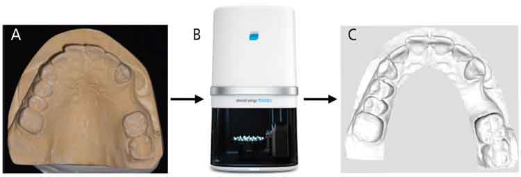
In some cases, the clinician can start with a conventional impression to transfer the details onto a stone cast model and perform an extraoral scan of the stone cast using intraoral scanning devices or dental laboratory scanners (Figures 5A through 5C). Laboratory scanners work by continuously projecting lines or patterns on the stone cast model surface. Reflection and distortion of the projected light are usually detected by one or more cameras that calculate the surface geometry. Inaccuracies with extraoral model scanning usually result from errors that occur during impression-taking and pouring of the stone cast.16
DIGITAL IMPLANT PLANNING AND DESIGN
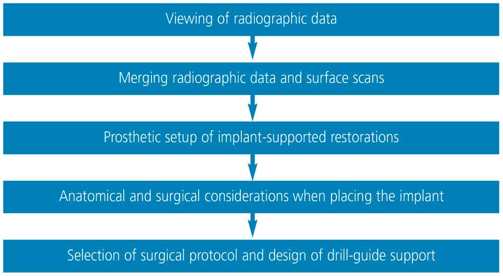
Once DICOM and STL data are acquired, implant planning software is utilized to plan the implant prosthesis and position. Although there may be some degree of variation in the order of the steps, the basic sequence is similar in all implant planning software. These steps are outlined in Figure 6.
Viewing of radiographic data — As noted, 3D volumetric data rendered from DICOM files is usually displayed as two-dimensional cross-sectional images: bucco-lingual (sagittal), anterior-posterior (axial), and mesiodistal (coronal; Figure 2). To better evaluate bone and dentinal structures for purposes of implant planning, these planes are segmented and a 3D model of bone and teeth is displayed (Figure 7).16
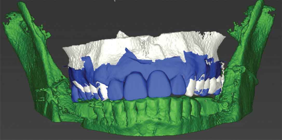
Merging radiographic data and surface scans — Because a 3D volumetric model reconstructed by segmentation of the CBCT data does not usually display teeth or soft tissue accurately, STL data derived from optical scans is merged with the 3D reconstructed model. Preferably, teeth surfaces on both data sets are used for merging. In cases in which a significant amount of scatter is present due to radiopaque materials in the dentition, clinicians can fabricate custom and standardized fiducial markers on a radiographic template, and these markers can be used as reference points to register multiple datasets.17 With these markers, CBCT scans need to be taken twice: with the patient wearing the radiographic template, and the template on its own. Both DICOM data sets are used in the merging process with the STL data. When tooth surfaces are used, only one CBCT scan is necessary. Merging should be done as accurately as possible since implant position will be planned based on the merged data. Any discrepancy in merging data sets will result in poor virtual implant planning and therefore improper implant positioning during surgical execution.18

Prosthetic setup of implant-supported restorations — Once the DICOM and STL data are merged, the implant-supported restoration is designed prior to implant placement to ensure a prosthetically driven implant position. The diagnostic setup can also be used for the final implant restoration. Many CAD programs are available to design the prosthesis. Some software will provide standard teeth shapes, additional shaping tools, and virtual articulators to facilitate accurate and efficient tooth setup. A conventional wax-up can also be made on a stone model and scanned extraorally before being incorporated in the implant planning software as an additional STL file to merge with the data sets (Figure 8). Whether teeth are designed with CAD software or a conventional wax-up will not affect the final outcome. However, additional time may be needed to do an extraoral scan and transfer the conventional wax-up stone model into a virtual model.
Anatomical and surgical considerations when placing an implant — Clinicians attempting to surgically place implants should have thorough knowledge of vital anatomical structures they may encounter during placement to avoid complications during surgery.19 When planning an implant virtually, clinicians must ensure that a minimum of 1.5 mm of bone is present buccal to the planned implant in order to achieve optimal esthetics and peri-implant soft tissue stability. In cases in which buccal bone is expected to be less than 1.5 mm, clinicians should consider performing a guided bone regeneration procedure to avoid future tissue recession, which could compromise peri-implant soft tissue esthetics.20 When an implant is planned adjacent to another implant, a 3 mm mesiodistal distance is needed between both implants.21 In terms of depth, the implant should be placed fully in bone and 3 to 4 mm apical to the planned prosthesis margin if it was bone level, or 1 to 2 mm apical from the planned prosthesis margin if it was a tissue-level design.22
Selection of surgical protocol and design of drill-guide support — Once implant position is determined, the surgical template is designed. Surgical templates are supported by three kinds of tissue: bone, mucosa or tooth.23 Whenever possible, clinicians are advised to use a tooth-supported template due to its superior accuracy.3 Additionally, it is recommended to use more than two adjacent teeth as support for the template, as this will increase stability.24 The use of bone-supported templates is slightly more invasive, since a mucoperiosteal flap must be reflected to expose the underlying bone, which, in turn, results in increased postoperative discomfort and possible bone loss due to decreased blood supply.25 In comparison, mucosa-supported templates are less invasive and can reduce postoperative pain, discomfort, surgical time and healing time.26 However, the limitations include their dependence on mucosal thickness and resilience.27 Additionally, clinicians can utilize the templates for the initial pilot drill or perform the procedure fully guided. Usually, fully guided protocols are recommended due to the higher accuracy of implant placement.2
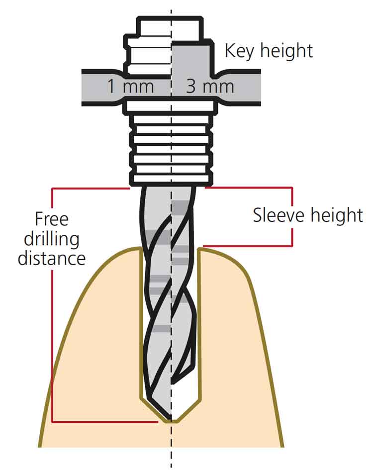
Drill guidance and deviation play a crucial role in the accuracy and outcome of sCAIS. Deviations were thought to be due to either one or a combination of factors: sleeve height, drilling distance or guided key height. These choices differ in various implant systems and are made either by the clinician or generated by the implant planning software. It has been shown that accuracy of sCAIS is directly related to the free drilling distance apical to the guided sleeve and inversely related to the guided key height used above the sleeve (Figure 9). Therefore, when clinically possible, a protocol involving a shorter drill, lower sleeve height and longer drill key may have more favorable outcomes on the accuracy of sCAIS.28
Additionally, some deviations can occur after osteotomy and during implant placement. This could be due to inaccuracies of the drill or use of different implant macro designs, or both. It has been found that tapered implant macro designs have statistically significant higher positional accuracy when compared to parallel implant macro designs. This can be attributed to the design of the drill, thread or insertion geometry.29
COMPUTER AIDED MANUFACTURING
The use of CAM technology brings the virtual design into reality. Additive or subtractive processes are utilized during manufacturing. Subtractive technology (i.e., milling) uses cutting instruments to shape material that comes from the manufacturer,30 while additive processes (i.e., 3D printers) utilize special ink materials and an energy source to build up layer by layer.31 The accuracy of surgical template production via subtractive or additive technology is comparable within a clinically acceptable range.32
Thanks to advances in dental materials and production methods, surgical templates can be fabricated in metal, zirconia or resin.33,34 The majority of surgical templates are made of 3D-printed resin due to ease in material accessibility and facilities in the clinic, ease of fabrication, and cost. However, the disadvantages are a thicker, bulkier template to compensate for the resin’s strength limitations. Bulkier templates limit accessibility, as well as the surgical view. By comparison, metal and zirconia are stronger than resin and do not need to be as thick, which enhances surgical visibility and access. The drawbacks of using metal or zirconia are the increased cost and manufacturing time of the surgical template.
The advent of digital workflows for implant treatment has increased accuracy and improved diagnosis, treatment planning and surgical execution in dental implant placement. In turn, these benefits have led to more predictable and successful implant outcomes.
KEY TAKEAWAYS
- Due to their advantages in accurate diagnosis, case planning and surgical execution, digital technologies are becoming more widely utilized in dental implant treatment.
- After implant positioning is planned according to the appropriate anatomical and prosthetic considerations, the clinician can start designing the surgical template to be used in the placement phase.
- Once the treatment planning data are merged, the implant-supported restoration is designed prior to implant placement to ensure a prosthetically driven implant position.
- Accuracy when merging data sets is critical, because any discrepancies will result in poor virtual implant planning and, thus, improper implant positioning during surgical execution.18
- Whenever possible, clinicians are advised to use a tooth-supported surgical template due to its superior accuracy over alternative support methods.3
- The advent of digital workflows for implant treatment has increased accuracy and improved diagnosis, treatment planning and surgical execution in implant placement, leading to more predictable outcomes.
REFERENCES
- Arunyanak SP, Harris BT, Grant GT, Morton D, Lin WS. Digital approach to planning computer-guided surgery and immediate provisionalization in a partially edentulous patientJ J Prosthet Dent. 2016;116:8–14.
- Van Assche N, Vercruyssen M, Coucke W, Teughels W, Jacobs R, Quirynen M. Accuracy of computer-aided implant placement. Clin Oral Implants Res. 2012;23(Suppl 6):112–123.
- Tahmaseb A, Wu V, Wismeijer D, Coucke W, Evans C. The accuracy of static computer-aided implant surgery: a systematic review and meta-analysis. Clin Oral Implants Res. 2018;29(Suppl 16):416–435.
- Halperin-Sternfeld M, Machtei EE, Horwitz J. Diagnostic accuracy of cone beam computed tomography for dimensional linear measurements in the mandible. Int J Oral Maxillofac Implants. 2014;29:593–599.
- Flügge T, van der Meer WJ, Gonzalez BG, et al. The accuracy of different dental impression techniques for implant-supported dental prostheses: a systematic review and meta-analysis. Clin Oral Implants Res. 2018;29(Suppl 16):374–392.
- Fokas G, Vaughn VM, Scarfe WC, Bornstein MM. Accuracy of linear measurements on CBCT images related to presurgical implant treatment planning: a systematic review. Clin Oral Implants Res. 2018;29(Suppl 16):393–415.
- Tyndall DA, Price JB, Tetradis S, et al. Position statement of the American Academy of Oral and Maxillofacial Radiology on selection criteria for the use of radiology in dental implantology with emphasis on cone beam computed tomography. Oral Surg Oral Med Oral Pathol Oral Radiol. 2012;113:817–826.
- Jacobs R, Salmon B, Codari M, Hassan B, Bornstein MM. Cone beam computed tomography in implant dentistry: recommendations for clinical use. BMC Oral Health. 2018;18:88.
- Menezes CC, Janson G, da Silveira Massaro C, Cambiaghi L, Garib DG. Precision, reproducibility, and accuracy of bone crest level measurements of CBCT cross sections using different resolutions. Angle Orthod. 2016;86:535–542.
- Schulze RK, Berndt D, d’Hoedt B. On cone-beam computed tomography artifacts induced by titanium implants. Clin Oral Implants Res. 2010;21:100–107.
- Hamilton A, Jamjoom F, Doliveux S, Gallucci GO, Friedland B. Radiographic markers for merging virtual data sets. J Prosthet Dent. 2019;122:5–9.
- Papaspyridakos P, Gallucci GO, Chen CJ, et al. Digital versus conventional implant impressions for edentulous patients: accuracy outcomes. Clin Oral Implants Res. 2016;27:465–472.
- Karl M, Graef F, Schubinski P, Taylor T. Effect of intraoral scanning on the passivity of fit of implant-supported fixed dental prostheses. Quintessence Int. 2012;43:555–562.
- Gan N, Xiong Y, Jiao T. Accuracy of intraoral digital impressions for whole upper jaws, including full dentitions and palatal soft tissues. PLoS One. 2016;11:e0158800.
- Abduo J, Elseyoufi M. Accuracy of intraoral scanners: a systematic review of influencing factors. Eur J Prosthodont Restor Dent. 2018;26:101–121.
- Kernen FF. Pre-operative analysis and treatment planning in digital implant dentistry. Forum Implantologicum. 2019;15:8.
- Katsoulis J, Pazera P, Mericske-Stern R. Prosthetically driven, computer-guided implant planning for the edentulous maxilla: a model study. Clin Implant Dent Relat Res. 2009;11:238–245.
- Flügge T, Derksen W, Te Poel J, et al. Registration of cone beam computed tomography data and intraoral surface scans — a prerequisite for guided implant surgery with CAD/CAM drilling guides. Clin Oral Implants Res. 2017;28:1113–1118.
- Greenstein G, Cavallaro J, Tarnow D. Practical application of anatomy for the dental implant surgeon. J Periodontol. 2008;79:1833–1846.
- Farronato D, Pasini PM, Orsina AA, et al. Correlation between buccal bone thickness at implant placement in healed sites and buccal soft tissue maturation pattern: a prospective three-year study. Materials (Basel). 2020;13:511.
- Tarnow DP, Cho SC, Wallace SS. The effect of inter-implant distance on the height of inter-implant bone crest. J Periodontol. 2000;71:546–549.
- Grunder U, Gracis S, Capelli M. Influence of the 3D bone-to-implant relationship on esthetics. Int J Periodontics Restorative Dent. 2005;25:113–119.
- Gallardo YN, da Silva-Olivio IR, Mukai E, et al. Accuracy comparison of guided surgery for dental implants according to the tissue of support: a systematic review and meta-analysis. Clin Oral Implants Res. 2017;28:602–612.
- El Kholy K, Lazarin R, Janner SF, et al. Influence of surgical guide support and implant site location on accuracy of static computer-assisted implant surgery. Clin Oral Implants Res. 2019;30:1067–1075.
- Rosenfeld AL, Mandelaris GA, Tardieu PB. Prosthetically directed implant placement using computer software to ensure precise placement and predictable prosthetic outcomes. Part 2: rapid-prototype medical modeling and stereolithographic drilling guides requiring bone exposure. Int J Periodontics Restorative Dent. 2006;26:347–353.
- Rosenfeld AL, Mandelaris GA, Tardieu PB. Prosthetically directed implant placement using computer software to ensure precise placement and predictable prosthetic outcomes. Part 3: stereolithographic drilling guides that do not require bone exposure and the immediate delivery of teeth. Int J Periodontics Restorative Dent. 2006;26:493–499.
- Cassetta M, Di Mambro A, Giansanti M, Stefanelli LV, Cavallini C. The intrinsic error of a stereolithographic surgical template in implant guided surgery. Int J Oral Maxillofac Surg. 2013;42:264–275.
- El Kholy K, Janner S, Schimmel M, Buser D. The influence of guided sleeve height, drilling distance, and drilling key length on the accuracy of static computer-assisted implant surgery. Clin Implant Dent Relat Res. 2019;21:101–107.
- El Kholy K, Ebenezer S, Wittneben JG, et al. Influence of implant macrodesign and insertion connection technology on the accuracy of static computer-assisted implant surgery. Clin Implant Dent Relat Res. 2019;21:1073–1079.
- Beuer F, Schweiger J, Edelhoff D. Digital dentistry: an overview of recent developments for CAD/CAM generated restorations. Br Dent J. 2008;204:505–511.
- Duda T, Raghavan LV. 3D metal printing technology. IFAC-PapersOnLine. 2016;49:103–110.
- Henprasert P, Dawson DV, El-Kerdani T, et al. Comparison of the accuracy of implant position using surgical guides fabricated by additive and subtractive techniques. J Prosthodont. 2020;29:534–541.
- Stansbury JW, Idacavage MJ. 3D printing with polymers: challenges among expanding options and opportunities. Dental Materials. 2016;32:54–64.
- Chen L, Lin WS, Polido WD, Eckert GJ, Morton D. Accuracy, reproducibility, and dimensional stability of additively manufactured surgical templates. J Prosthet Dent. 2019;122:309–314.
Wei-Shao Lin, DDS, PhD, discloses previous honoraria from Straumann (although not in connection with this article). The other authors have no commercial conflicts of interest to disclose.
From Decisions in Dentistry. May 2021;7(5)12-14,16-17.
Leave a comment